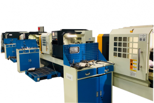
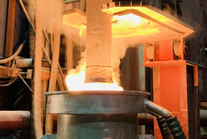
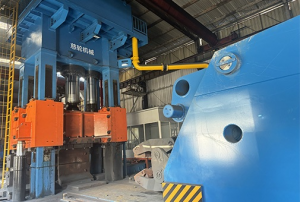
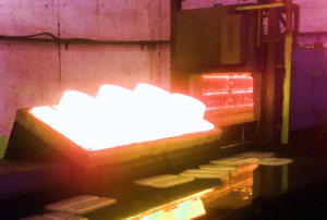
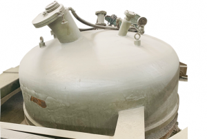
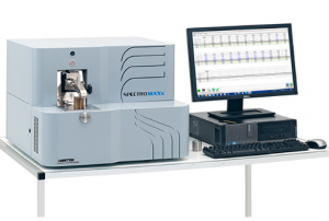
The company specializes in providing impeller products for famous European and American air compressor brand manufacturers and domestic wind turbine manufacturers. Committed to the production of stainless steel and aluminum-titanium alloy raw materials for high-speed impellers, as well as impeller blanks and finished products. The company has a history of nearly 30 years. It is located in the Wusong Economic Development Zone of Yangxing, Baoshan District. It covers an area of 15,000 square meters and has professional production equipment and technical production team. The company focuses on high-end advanced manufacturing and continuous innovation and development. The company relies on vacuum refining, electroslag, heat treatment, multi-axis CNC machining and various aspects of inspection and other excellent manufacturing processes and technologies to ensure product quality in all production links from raw materials to finished products, and is in a leading position in the same industry.
Open impeller replacement for Clivet centrifugal air compressor
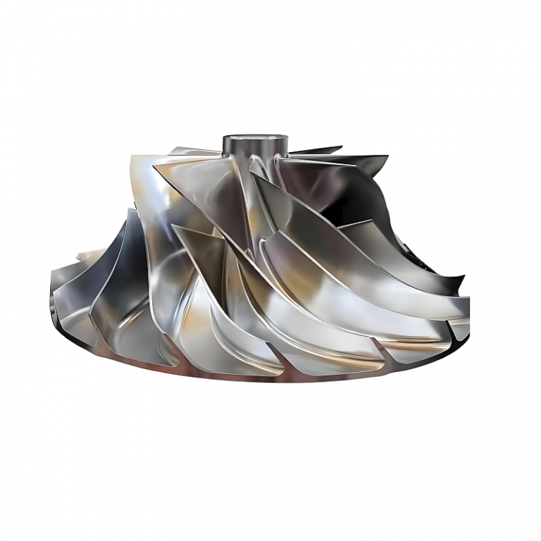
Open impeller replacement for Clivet centrifugal air compressor That call at 3:00 AM never brings good news. It was the plant air supervisor: “The Clivet centrifugal tripped on high vibration again. We pulled the inlet guide vanes — the open impeller’s got blade pitting and a chunk missing on the exducer side.” If you’ve managed a Clivet centrifugal air compressor for any length of time, you know that the open impeller is the heartbeat of the machine. When it fails, plant pressure drops, production stalls, and someone in procurement needs to find the right replacement yesterday — without paying a king’s ransom or waiting four months. This guide is built for that person — and for the maintenance tech who will install the part. No fluffy theory. Just what actually matters when sourcing and replacing an open impeller on a Clivet centrifugal air compressor. What makes the
Centrifugal impeller replacement for Sintec air compressor
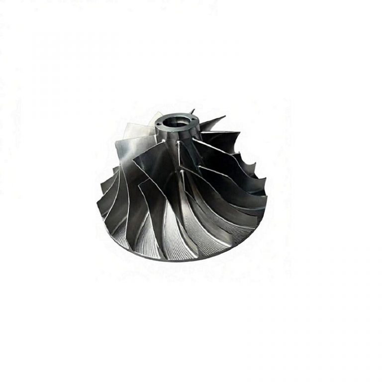
Centrifugal impeller replacement for Sintec air compressor If you’ve landed here, chances are your Sintec centrifugal compressor is down, the open impeller has been flagged during a vibration audit or a scheduled teardown, and now the clock is ticking. Maybe you’re in procurement trying to source a replacement that won’t eat up six months of maintenance budget. Maybe you’re the lead tech staring at pitted blades and wondering whether you can risk an aftermarket copy or have to swallow the OEM’s lead time. Both perspectives matter, because getting the wrong open impeller onto a Sintec machine doesn’t just sacrifice efficiency — it can back a whole plant into a corner. I’ve seen it both ways: the rush order that arrived with beautiful surface finish but the wrong back-face clearance, and the perfectly machined impeller that was forgotten to be dynamically balanced to the rotor’s actual service speed. That’s
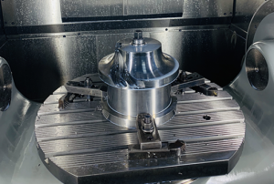
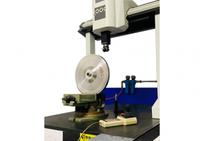
High accuracy multi-axis machining solution for impellers
CD Centrifugal Impeller High accuracy multi-axis machining solution for impellers Last year, a maintenance supervisor at a compressed air plant called us with a problem that sounded all too familiar. Their new set of open centrifugal impellers had been running for less than three weeks before vibration alarms forced an unplanned shutdown. The delivery came with a glossy CMM report — every dimension comfortably within the ±0.05 mm band on the drawing. Yet two impellers were already scrap, and the rest needed rebalancing. “What are we missing?” he asked. The answer, as we dug in, was hidden in the margins between “in tolerance” and “airworthy.” For open impellers on high-speed air compressors, a conventional multi-axis machining approach that only chases blueprint numbers routinely leaves behind uneven blade mass, inconsistent surface integrity, and awkward residual unbalance that no amount of bench blending can truly fix. That episode crystallized why
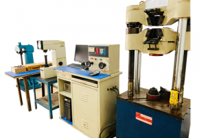
How often should you switch centrifugal open compressor impeller to avoid fatigue?
CD Centrifugal Impeller How often should you switch centrifugal open compressor impeller to avoid fatigue? About eight years ago, I got a 2 a.m. call from a plant manager whose 2,500-tonne centrifugal air compressor had just tripped. The vibration spike was so violent it sheared the probes. When we pulled the inlet, the open impeller looked like a metal flower that had bloomed — two blades had separated, and a third was hanging by a sliver. The root cause was textbook high-cycle fatigue. What stung wasn’t the cost of the impeller itself; it was the seven weeks of lost production while the OEM built a replacement and the procurement team scrambled. That night, nobody cared about the price per kilo of 17-4PH stainless steel. They wanted to know: how do we make sure this never happens again — and how often should we be switching this open impeller before fatigue sneaks up
What does back sweep refer to for centrifugal compressor impeller?
CD Centrifugal Impeller What does back sweep refer to for compressor impeller? Pick up a centrifugal compressor impeller and rotate it slowly under the light. The way the blades lean away from the direction of rotation at the outer edge — that gentle backward curve — isn’t a styling choice. That geometry is back sweep, and if you are sourcing custom impellers for air compressors or maintaining a fleet of machines, ignoring this one feature can quietly burn through your budget with surging, overspeed trips, and excess power draw. This article walks through what back sweep actually means and why it lands squarely in the middle of procurement specs and repair work instructions. Back sweep: the angle that controls your compressor’s personality In plain terms, back sweep (often written as backsweep) describes the blade exit angle measured relative to the radial direction. Imagine a straight line from the centre of the
What is the back-to-back impeller arrangement?
CD Centrifugal Impeller What is the back-to-back impeller arrangement? It’s 2 a.m. and a process air compressor just tripped on high thrust bearing temperature. The vibration guy stares at the trend, muttering about an axial shift. When the cartridge finally lands on the shop floor, you see it: two impellers facing opposite directions, their inlets looking away from each other like bookends on the same shaft. That’s a back-to-back impeller arrangement — and if you know how it lives and breathes, you’ll fix the machine faster, buy the right parts the first time, and stop leaving bearing life on the table. For procurement managers sourcing custom centrifugal impellers, and for the maintenance teams that have to live with those parts after the purchase order is closed, understanding this design isn’t a nice-to-have. It’s the difference between a rotor that runs for years and one that eats thrust pads
Custom CNC Titanium Turbine Water Pump Impeller Wheel
CD Centrifugal Impeller Custom CNC Titanium Turbine Water Pump Impeller Wheel It was a Wednesday afternoon when the phone rang. On the line was a maintenance lead from a busy air compressor house. His voice had that particular mix of urgency and exhaustion—the sound of a man who’d already been chasing a problem for two days. A coolant water pump inside one of their rotary screw compressors had torn itself apart. The cast iron centrifugal impeller looked like it had been chewed up. The factory replacement? Six weeks out, and the line was bleeding money. “Can you make us a new impeller from titanium, and can you make it fast?” he asked. That was the project that got us deep into what a real custom CNC titanium turbine water pump impeller wheel can do—not just as a stopgap, but as a permanent upgrade. If you’re a procurement manager
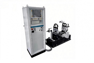
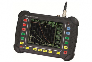
How to perform flaw detection on a centrifugal impeller specifically designed for air compressors?
CD Centrifugal Impeller How to perform flaw detection on a centrifugal impeller specifically designed for air compressors? You’ve just taken delivery of a replacement centrifugal impeller for your plant’s critical process-air compressor, or you’re staring at a pulled rotor during a major overhaul. The paperwork says the forging is sound and the dynamic balance is within ISO G 2.5. But you can’t shake one question: are there any hidden flaws waiting to turn this precision component into shrapnel at 35,000 rpm? For a procurement manager responsible for six-figure rotating assemblies, and for the hands-on reliability team that has to sign off on installation, generic quality certificates aren’t enough. You need a flaw detection regimen that is specific, verifiable, and built around the unique geometry and materials of a compressor impeller. This isn’t a generic NDT checklist you can copy from a pressure-vessel code. Centrifugal impellers for air compressors
What does back sweep refer to for compressor impeller?
CD Centrifugal Impeller What does back sweep refer to for compressor impeller? If you’ve ever spread three compressor impeller quotes across your desk and noticed one vendor pushing “30° back sweep” while another simply stamps “standard radial,” you already know the feeling. It’s that nagging doubt: Am I paying extra for a buzzword, or is this the thing that keeps my process running on a summer Friday night? For both procurement managers watching capital budgets and maintenance teams chasing mean time between repairs, back sweep isn’t just aerodynamic jargon. It’s one of those geometry details that quietly decides how much power you burn, how low the flow can go before the machine bucks, and whether a replacement impeller fits or fights the rest of your compressor. Let’s unpack it in plain terms, then get into the specifics that will save you money and downtime. Back Sweep – The 30-Second
Precision blanks(Preturn)for centrifugal impellers for air compressors
CD Centrifugal Impeller Precision blanks(Preturn)for centrifugal impellers for air compressors I remember the first time a supplier handed me a “precision blank” that turned out to be a raw forging with a half-hearted skim pass on the OD. My lead machinist held it up and asked if we were supposed to finish it or perform an autopsy. Since then, I’ve made it my mission to help procurement teams understand what a real precision blank — or, as some mills label it, a Preturn — actually needs to deliver when you’re buying centrifugal impeller bodies for air compressors. If you own the budget for impeller manufacturing, you already know the pain points: material costs that swing with nickel prices, five-axis capacity that’s perpetually overbooked, and quality escapes that don’t reveal themselves until the part is spinning at 40,000 rpm on the test stand. The blank you buy isn’t just a lump
