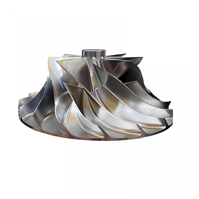
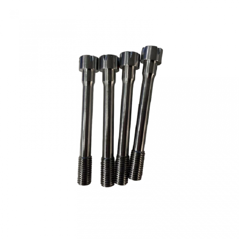
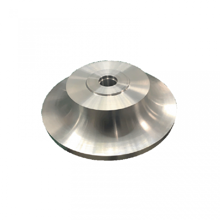
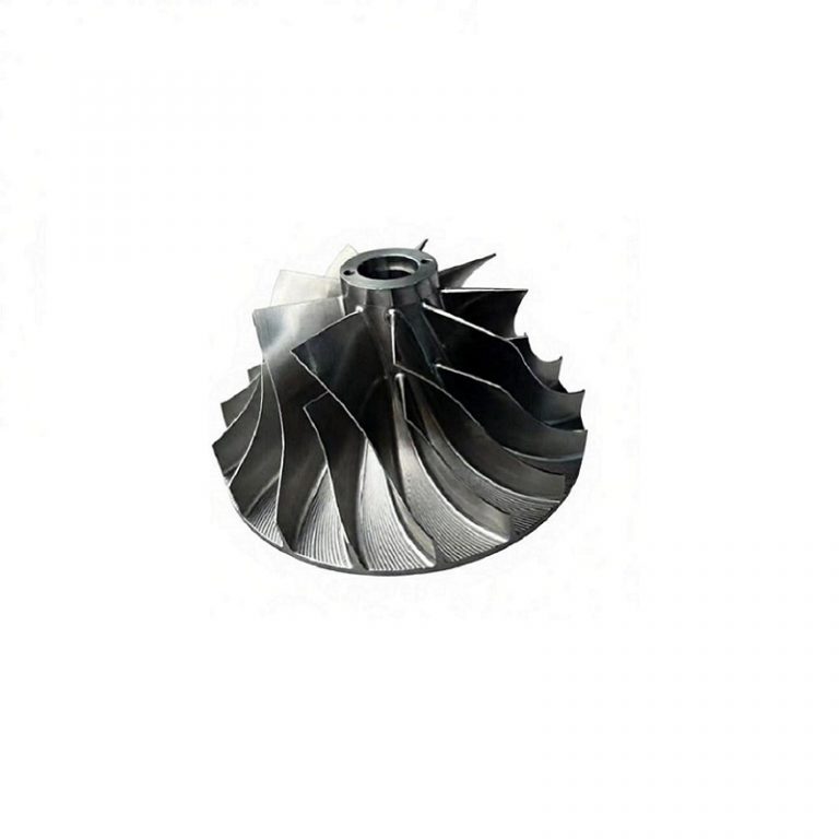

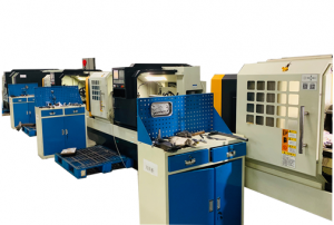
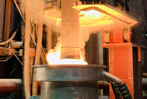
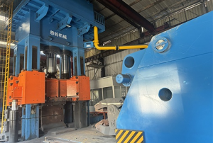
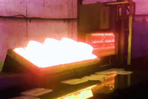
The company specializes in providing impeller products for famous European and American air compressor brand manufacturers and domestic wind turbine manufacturers. Committed to the production of stainless steel and aluminum-titanium alloy raw materials for high-speed impellers, as well as impeller blanks and finished products. The company has a history of nearly 30 years. It is located in the Wusong Economic Development Zone of Yangxing, Baoshan District. It covers an area of 15,000 square meters and has professional production equipment and technical production team. The company focuses on high-end advanced manufacturing and continuous innovation and development. The company relies on vacuum refining, electroslag, heat treatment, multi-axis CNC machining and various aspects of inspection and other excellent manufacturing processes and technologies to ensure product quality in all production links from raw materials to finished products, and is in a leading position in the same industry.

Turbine Compressor Impeller Design and Function
Turbine Compressor Impeller Design and Function "Turbine Compressor Impeller" is a key component in turbocharging and various industrial applications. Let's break it down clearly. Core Concept A Turbine Compressor Impeller (more accurately called a "Compressor Wheel" or "Compressor Impeller") is the rotating component within the compressor side of a turbocharger or centrifugal compressor. Its job is to draw in, accelerate, and compress air before it's forced into the engine's intake manifold. Think of it as a high-speed fan. The turbine wheel (on the hot exhaust side) and the compressor impeller (on the cold intake side) are connected by a common shaft. Exhaust gas spins the turbine, which directly spins the compressor impeller, compressing the intake air. Key Parts & Design Features Hub: The central body that mounts to the shaft. Blades/Vanes: The aerodynamic airfoils that do the work of moving the air. Their design is critical for efficiency and performance. Inducer: The inner, leading edge of the blades
Turbo Compressor Wheel Design and Function Explained
Turbo Compressor Wheel Design and Function Explained The turbocharger compressor wheel is the beating heart of forced induction. Let's break down what it is, how it works, and why it's so critical. What is a Turbo Compressor Wheel? It's the radial turbine (impeller) located on the cold side (intake side) of a turbocharger. Its sole job is to compress ambient air and force it into the engine's intake manifold at a higher density, allowing more oxygen to enter the cylinders for a more powerful combustion event. It is directly connected by a shaft to the turbine wheel (on the hot, exhaust side). Exhaust gases spin the turbine, which spins the compressor wheel. Key Design Features & Terminology Inducer Diameter: The smaller diameter at the eye (inlet) where air first enters. Exducer Diameter: The larger outer diameter where the compressed air exits into the compressor housing volute. Blades/vanes: The aerofoil-shaped fins. Their number, angle (backward swept, forward
Centrifugal Compressor Impeller Machining Complexities
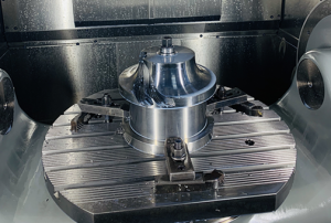
Centrifugal Compressor Impeller Machining Complexities Machining centrifugal compressor impellers is one of the most complex and demanding tasks in precision manufacturing. These components are critical for efficiency and reliability in applications like turbochargers, jet engines, and industrial compressors. Here’s a detailed breakdown. Core Challenges in Impeller Machining Complex Geometry: 3D hub surfaces, twisted blades (often with undercuts), thin leading/trailing edges, and tight blade-to-blade channels. High Accuracy & Surface Finish: Aerodynamic performance depends on precise blade profiles and smooth surfaces (often Ra < 0.8 µm) to minimize flow losses. Material Difficulty: Made from high-strength materials like: Titanium Alloys (e.g., Ti-6Al-4V): For high strength-to-weight ratio, but difficult to machine (low thermal conductivity, work hardening). Aluminum Alloys (e.g., 7075): For lightweight applications. Nickel-Based Superalloys (e.g., Inconel 718): For high-temperature applications (jet engines), extremely tough on cutting tools. Stainless Steels (e.g., 17-4PH): For corrosive environments. Rigidity Issues: Thin blades and long overhangs during machining are prone to chatter and
Centrifugal Chiller Impeller Design and Performance
Centrifugal Chiller Impeller Design and Performance The impeller is the absolute heart of a centrifugal chiller, the rotating component that does the fundamental work of compressing the refrigerant. Its design and performance are directly linked to the chiller's efficiency, capacity, and stability. Here’s a comprehensive breakdown of the centrifugal chiller impeller: Core Function The impeller's job is to convert the rotational kinetic energy from the electric motor, steam turbine, or gearbox into pressure (head) and velocity in the refrigerant vapor. It accelerates low-pressure, low-density refrigerant gas from the evaporator outward and radially, increasing its pressure and temperature before it enters the diffuser and condenser. Key Design Characteristics & Types Modern centrifugal chillers almost exclusively use backward-curved, backward-inclined, or airfoil-shaped impellers. The old forward-curved designs are obsolete due to poor efficiency and instability. Backward-Curved/Inclined Blades: Geometry: The blades curve or incline opposite the direction of rotation. This is the most common design in
Electroslag for alloy metal material of centrifugal impeller
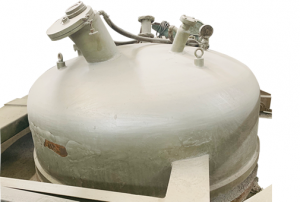
Electroslag for alloy metal material of centrifugal impeller The use of Electroslag Remelting (ESR) for alloy metal materials in centrifugal impellers is a critical advanced manufacturing process that directly addresses the demanding performance requirements of these components. Here’s a detailed breakdown of why, how, and what benefits ESR provides for centrifugal impeller alloys. 1. The Challenge: Demands on a Centrifugal Impeller A centrifugal impeller (used in turbochargers, aircraft engines, compressors, and pumps) operates under extreme conditions: High Rotational Speeds: Subject to immense centrifugal forces. High Temperatures: Especially in turbine engines and turbochargers. Cyclic Fatigue: Constant stress cycles leading to potential crack initiation. Corrosive/High-Pressure Environments: Exposed to hot, aggressive gases or fluids. Requirement for High Strength-to-Weight Ratio: Especially in aerospace. To meet these demands, impellers are often made from high-performance alloys: Nickel-based superalloys (e.g., Inconel 718, 713LC) Titanium alloys (e.g., Ti-6Al-4V) High-strength stainless steels (e.g., 17-4 PH, Custom 450) The quality and homogeneity of these alloy ingots are paramount. Any internal defects (like
Centrifugal Blower Impeller Design and Applications
Centrifugal Blower Impeller Design and Applications The centrifugal blower impeller is the beating heart of any centrifugal blower or fan. It's the rotating component that converts mechanical energy (from a motor) into kinetic energy and pressure in the air or gas. Here’s a comprehensive breakdown of centrifugal blower impellers: Core Function As the impeller rotates, it draws air axially into its eye (center). The air is then captured by the blades, accelerated radially outward due to centrifugal force, and finally expelled at high velocity and increased pressure into the volute (housing casing), which converts the velocity into static pressure. Key Design Characteristics 1. Blade Types & Performance Curves The blade design is the primary factor determining the fan's performance characteristics (pressure vs. flow). Forward-Curved (FC) / Multi-Vane (Squirrel Cage): Blades: Many short blades, curved in the direction of rotation. Performance: Lower speed, generates high volume flow at moderate static pressures. Its performance
Best Materials for Centrifugal Impellers
Best Materials for Centrifugal Impellers The "best" material for a centrifugal impeller depends entirely on the specific application, operating conditions, and performance requirements. There is no single "best" material, but there is a best material for a given job. Here’s a breakdown of the most common materials, their advantages, disadvantages, and typical applications. Key Selection Criteria: Corrosion/ Erosion Resistance: Against the pumped fluid (acids, seawater, slurries). Strength & Fatigue Resistance: To withstand centrifugal forces at high RPM. Weight: Affects bearing life and rotor dynamics. Cost: Material and manufacturability (casting, machining). Temperature: For hot or cryogenic services. Common Materials and Their Applications 1. Stainless Steels (The Most Common Category) Types: 304/304L, 316/316L, Duplex (2205), Super Duplex (2507), 17-4 PH (precipitation-hardening). Advantages: Excellent all-around corrosion resistance, good strength, readily available, cost-effective for many services. Disadvantages: Can be heavy; not suitable for very strong acids or chlorides without careful selection. Best For: The vast majority of general industrial applications (water,
Centrifugal Blower Impeller Design and Function Overview
Centrifugal Blower Impeller Design and Function Overview Here is a comprehensive overview of a centrifugal blower impeller, covering its function, design, types, key considerations, and common applications. Core Function The impeller is the rotating heart of a centrifugal blower (or fan). Its primary function is to transfer energy from the motor to the air/gas by accelerating it radially outward. It converts rotational kinetic energy into static pressure and kinetic energy in the air stream. How It Works (The Principle) Air Intake: Air enters the impeller axially (parallel to the shaft) through the eye (the center inlet). Acceleration: The rotating blades (vanes) capture the air. Centrifugal force flings the air radially outward into the scroll (volute) casing. Pressure Rise: As the air moves from the small-radius eye to the large-radius tip, its velocity increases dramatically. This high-velocity air then enters the expanding volute casing, where velocity is converted into static pressure (Bernoulli's principle). Discharge: The pressurized
Types and Functions of Centrifugal Pump Impellers
Types and Functions of Centrifugal Pump Impellers Impellers are the heart of a centrifugal pump, and their design directly determines the pump's performance, efficiency, and suitability for an application. They are classified in three primary ways: 1. Based on Flow Direction (Path of Fluid Through Impeller) This is the fundamental classification. Radial Flow Impeller: The most common type. Fluid enters axially and is discharged radially (90° to the shaft). Generates high head at low flow. Used in most standard centrifugal pumps for water supply, industrial processes, and high-pressure applications. Mixed Flow Impeller: Fluid enters axially and is discharged at an angle (between 0° and 90°). Provides a balance of moderate flow and moderate head. Often used in irrigation, drainage, and larger water circulation pumps. Axial Flow Impeller (Propeller): Fluid enters and discharges nearly parallel to the shaft (axial direction). Designed for very high flow rates at very low head. Common in stormwater pumping, flood control, and large-scale circulation
What are the functions of a centrifugal impeller in a centrifugal air compressor?
CD Centrifugal Impeller What are the functions of a centrifugal impeller in a centrifugal air compressor? The centrifugal impeller is the heart of a centrifugal air compressor, and its functions are all centered around converting mechanical energy into pneumatic energy. Here are its primary functions, broken down: Core Functions: 1. Energy Transfer & Conversion Primary Role: The impeller takes mechanical energy (rotational motion and torque from the driver, typically an electric motor or turbine) and transfers it to the air. Conversion: It converts this mechanical input energy into kinetic energy (velocity) and pressure energy (pressure). 2. Acceleration of Air / Imparting Velocity As the impeller rotates at high speeds (often 20,000 - 100,000+ RPM), the curved blades (vanes) grab the air that is drawn axially into the eye (center) of the impeller. The air is forced to move radially outward along the blade passages. Due to the impeller's high rotational speed and the centrifugal
